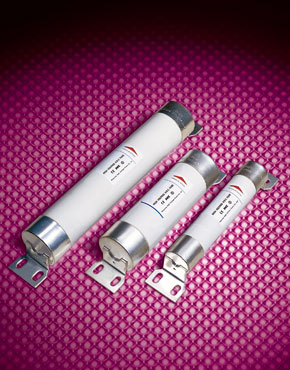
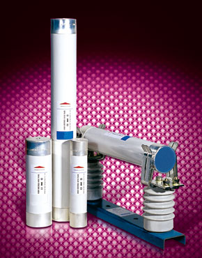
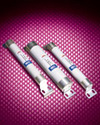
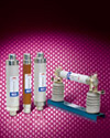
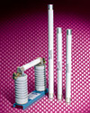
H.V. HRC Current-Limiting Fuses type W for Motor Protection

Applications
- H.V HRC current-limiting fuses type W for motor protection is mainly used in AC 50Hz, rated voltage 3.6-10kV, rated current up to400A(3.6kV), 224A(7.2kA) circuit for protecting motor and power equipment from overload and short-circuit.
- It can also be used with load switch; vacuum contact it conforms to IEC282-1, IEC644, BS and GB15166.2.
Design Features
- W type H.V HRC current-limiting fuses have two installations: bus-bar installation and insert installation. It is small in volume, reliable in connection. The power striker parallels to the fuse element made from pure silver. They are sealed in the fuse tube filled with chemically treated high-purity quartz sand. The fuse tube is made from heat resistant, high duty ceramic or epoxy glass. When fault circuit happens. The fuse link melts, the high-resistant metal wire paralleling to fuse links melts immediately at the appearance of the arc, and the striker jumps out to push the chained equipment contact, signaling the melting or automatically cutting the circuit. W type H.V HRC current-limiting fuses have many merits as high current-limiting ability, high breaking capacity, quick and punctual in action, reliable in performance.
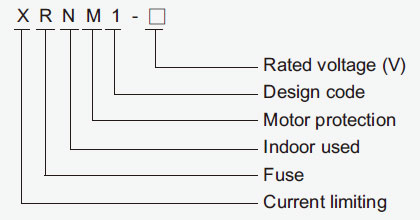
Mode And Implication
Cross-reference:

Department Model:
Basic Data
| Models |
Ratedvoltage (KV) |
Rated current of the fuse links(A) |
Rated breakingcurrent (KA) |
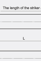
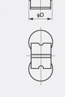
Dimensions (mm) Figure 1 |
Weight (Kg) |
| Foreign |
Department |
Fig. |
ΦD |
L |
| WDF.O |
XRNM1 |
3.6 |
50, 63, 80, 100,125 |
50 |
Figure 1~2 |
51 |
254 |
1.4 |
| WFF.O |
XRNM1 |
3.6 |
100, 125, 160, 200 |
50 |
76 |
254 |
2.8 |
| WKF.O |
XRNM1 |
3.6 |
250, 315, 355, 400 |
50 |
76 |
254 |
2.8 |
| WFN.O |
XRNM1 |
7.2 |
25, 31.5, 40, 50, 63, 80, 100, 125, 160 |
40 |
76 |
403 |
4.15 |
| WKN.O |
XRNM1 |
7.2 |
200, 224 |
40 |
76 |
403 |
4.15 |
| |
XRNM1 |
10 |
25, 31.5, 40, 50, 63, 80, 100, 125, 160, 200, 224 |
40 |
76 |
600 |
5.26 |
Note:
Under stipulated condition, min.breaking current of fuses could be as high as 2.5~3.0 times than rated current.
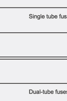
7.2KV fuse link of 224A or above have a dual-tube body
3.6KV fuse link of 400A or above have a dual-tube body
Dimensions
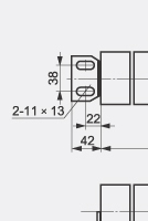
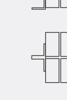
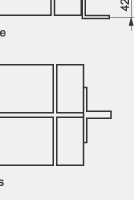
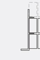
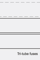
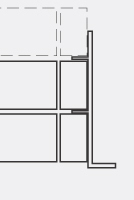
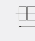
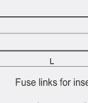
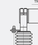
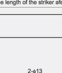
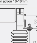
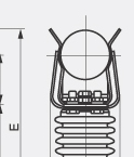
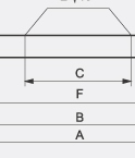
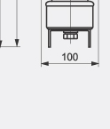
Figure 1 fuses for busbar installation
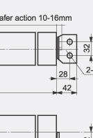
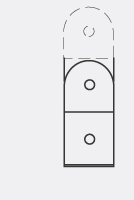
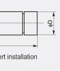
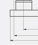
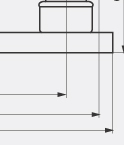
Figure 2 fuses for insert installation
Dimension of moto protection fuse type W for busbar installation(mm)
| Model |
Dimensions |
| A |
B |
C |
G |
E |
F |
| WFF.O |
390 |
312 |
340 |
140 |
246 |
209 |
| WKF.O |
390 |
312 |
340 |
140 |
246 |
209 |
| WFN.O |
500 |
461 |
150 |
160 |
266 |
358 |
| WKN.O |
500 |
461 |
150 |
160 |
266 |
358 |
| XRNM1 |
690 |
659 |
350 |
160 |
266 |
555 |
Selection for W type motor current-limit fuse box
When started with full voltage, Rated current ≈ twice of loaded motor current; When started under other circumstances, rated current ≈ times of loaded motor current. For directly started motor, fuses of proper rated current should be selected according to the following formula;
Iy=N.In.Φ
- Iy for Starting current
- N for Ratio of starting current and loaded current, usually N ≈ 6
- In for Loaded motor current
- Φ for Comprehensive cofficient, see following table.
| Φ Comprehensive cofficient |
| Start times |
2 |
4 |
8 |
16 |
| Φ |
1.7 |
1.9 |
2.1 |
2.3 |
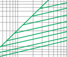
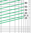
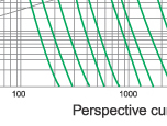
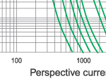
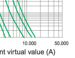
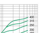
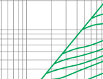
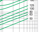
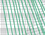
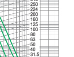
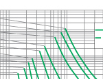
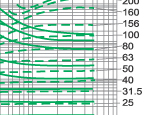
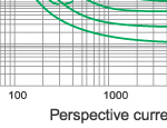
Refer to time-current characteristice diagram for selection of proper H.V. fuse link, Rated current of fuse link should be 1.3 times thanloaded motor current.
Characteristics Curve
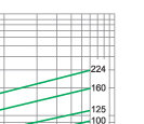
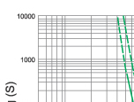
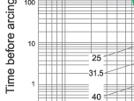
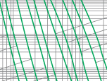
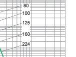
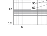
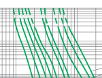
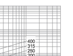
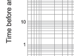
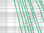
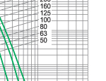
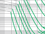
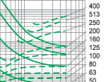
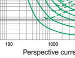
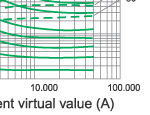
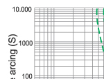
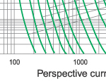
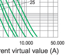
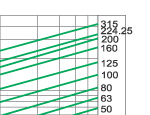
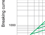
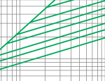
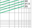
Time-current characteristics of 10KV fuse links type XRNM1
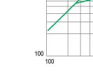
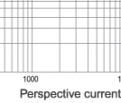
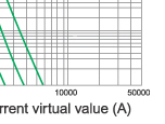
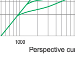
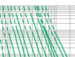
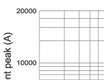
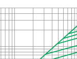
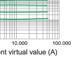
Cut-off current characteristics of 10KV fuse links type XRNM1
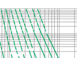
Time-current characteristics of 3.6KV fuse links
Cut-off current characteristic of 3.6KV fuse links
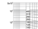
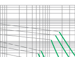
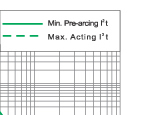
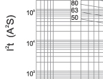
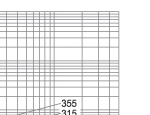
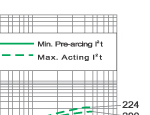
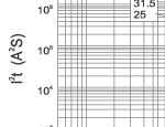
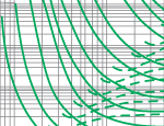
I2.t characteristics of 3.6KV fuse links
Time-current characteristics of 7.2KV fuse links
Cut-off current characteristic of 7.2KV fuse links
I2.t characteristics of 7.2KV fuse links


