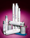
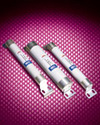
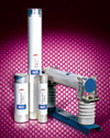
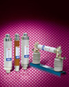
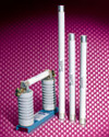
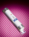
H.V. HRC Current-Limiting Fuses type W for Motor Protection
Applications
- H.V HRC current-limiting fuses type F for transformer protection is mainly used in AC 50Hz, rated voltage up to 24kV, rated current160A circuit for protection transformers and power equipment from overload and short-circuit.
- It conforms to IEC282-1, BS, DIN and GB15166.2.
Design Features
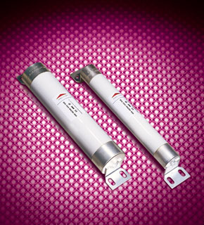
- F type H.V HRC current-limiting fuses have two installations: Bus-bar installation and insert installation, It is small in volume, reliable in connection and convenient in install and removal. The striker parallels to the fuse element made from pure silver. They are sealed in the fuse tube filled with chemically treated high-purity quartz sand. The fuse tube is made from heat resistant, high duty ceramic or epoxy glass. When fault circuit happens, the fuse link melts, the high-resistant metal wire paralleling to fuse links melts immediately at the appearance of the arc, and the striker jumps out to push the chained equipment contact, signaling the melting or automatically cutting the circuit. The striker has spring type and powder type. Spring type strikers use the energy released by spring to push the striker; Powder type strikers use high pressure caused by the lighting powder to push the striker. F type fuse can reliably break the fault circuit which causes the fuse link to melt and which is up to the rated breaking current. It is not only featured with high breaking capacity of the current-limiting fuses, but also with protection of low overload of the un-current-limiting fuses. F type fuse had a protection of full scope breaking capacity.
Mode And Implication
-
Conform to DIN standard

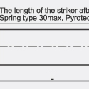
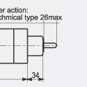
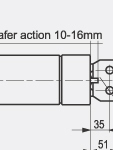
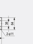
| Models | Rated votlage(KV) | Rated current of fuse link(A) | Rated breakingcurrent (KA) | Dimensions (mm) Figure 1 | Weight (kg) | |
| ΦD | L | |||||
| FDL.J | 12 | 6.3, 10, 16, 20, 25, 31.5 | 50 | 51 | 292 | 1.47 |
| FFL.J | 12 | 40, 50, 63 | 50 | 76 | 292 | 3.15 |
| FXL.J | 12 | 80, 100 | 50 | 88 | 292 | 4.15 |
| FDM.J | 24 | 6.3, 10, 16, 20, 25, 31.5 | 35.5 | 51 | 442 | 2.7 |
| FFM.J | 24 | 25, 31.5, 40, 45 | 35.5 | 76 | 442 | 4.5 |
-
Conform to BS standard
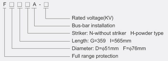
| Models | Rated votlage(KV) | Rated current of fuse link(A) | Rated breakingcurrent (KA) | Dimensions (mm) Figure 2 | Weight (kg) | |
| ΦD | L | |||||
| FFGHA | 12 | 10, 16, 20, 25, 31.5, 40, 50, 63 | 40 | 76 | 359 | 4.0 |
| FDIHA | 24 | 3.15, 5, 6.3, 10, 16, 20, 31.5 | 35.5 | 51 | 565 | 3.0 |
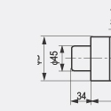
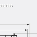
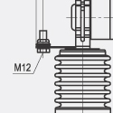
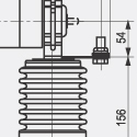
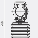
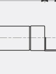
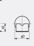
Dimensions
 |
 |
 |
 |
 |
 |
 |
 |
 |
 |
 |
 |
 |
 |
 |
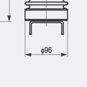 |
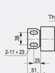 |
 |
 |
 |
 |
 |
 |
 |
I2t Characteristics of Full-range H.V. Current-limiting Fuses Type F
| Rated working voltage(KV) | Rated working current(A) | Min.prearcing I2.t(A2.S) | Max. melting I2.t(A2.S) |
| 12 | 10 | 2.2x10² | 4.7x10³ |
| 12 | 16 | 3.4x10² | 6.1x10³ |
| 12 | 20 | 7.7x10² | 1.1x10⁴ |
| 12 | 25 | 1.3x10³ | 1.6x10⁴ |
| 12 | 31.5 | 2.5x10³ | 2.5x10⁴ |
| 12 | 40 | 3.8x10³ | 3.8x10⁴ |
| 12 | 50 | 6.8x10³ | 5.6x10⁴ |
| 12 | 63 | 8.1x10³ | 8.4x10⁴ |
Selection of Proper Full-range H.V. Fuses Type F for Transformer Protection
| Capacity of transformer(KVA) | Primary voltage of transformer 12KV | ||
| Fuse models (It conforms to DIN and BS) | Rated current of fuse link(A) | ||
| ≤125 | FDL.J-12 | FFGHA-12 | 10 |
| 160 | FDL.J-12 | FFGHA-12 | 16 |
| 200 | FDL.J-12 | FFGHA-12 | 20 |
| 250 | FDL.J-12 | FFGHA-12 | 20 |
| 315 | FDL.J-12 | FFGHA-12 | 25 |
| 400 | FDL.J-12 | FFGHA-12 | 31.5 |
| 500 | FFL.J-12 | FFGHA-12 | 40 |
| 630 | FFL.J-12 | FFGHA-12 | 50 |
| 800 | FFL.J-12 | FFGHA-12 | 63 |
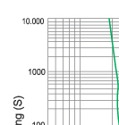
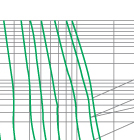
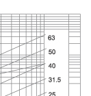
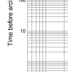
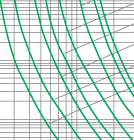
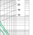
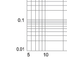
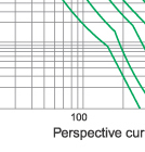
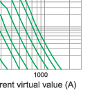
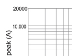
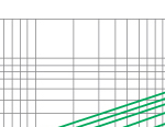
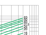
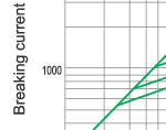
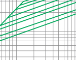
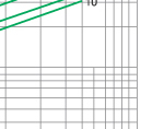
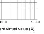
Characteristics Curve
 |
 |
 |
 |
 |
 |
 |
 |
 |
 |
 |
 |
 |
 |
 |
 |
 |
 |

