Current Transformer
Introduction
Current Transformer was used to change the high primary current to low secondary current. Connected with the panel meter or relay, they can help to measure the current or protect the equipments which were connected to the high voltage line.
Selection of the Current Transformer
To select the Current Transformer correctly, the following points should be clarified:
- The application(for measuring or protection)
- The features of the working environment (indoor or out door, operating temperature, air humidity etc..)
- Operation voltage and frequency
- Range of the primary current (max. and min. of the current to be measured)
- Dimension of the cable or busbar
- Data of the overload
- Short circuit current
- Specification of the measuring device associated with the current transformer (accuracy, rated current, consumption etc..)
- The diameter and length or the cable which was used to connect the current transformer and associated measuring device
Power Losses Of The Current Transformer
- In the practical application, the power generated by the primary current should be equal or bigger than the power requirement of the associated measuring device plus the consumption of the connecting line.
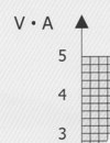
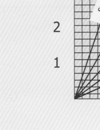
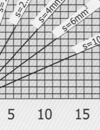
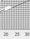
- Losses in the line, PL:
This is the power lost, through heat, generated by the passage of current through the resistance RL in the cables, in the transformer secondary circuit.
- Factors to be taken into account:
Secondary current: PL = RL ./2
Cable diameter: RL is inversely proportional to the square of the diameter
Cable length: RL is proportional to the length of cabling (there and back)
- Power:
The nominal apparent power (V.A) with a specified power factor, which was supplied by the current transformer, to the secondary Current with the assigned current when it’s connected to its nominal load, sc (V.A) = Zc . (/sn)2
According to standards, for apparent power greater than or equal to 5 v.a, the power factor is 0.8 inductive. For apparent power less than 5 V.A the power factor is considered to be one.
Table of Losses in the Secondary Line
Note: With .../1A transformers losses are reduced 25times
Length of secondary line
Accuracy of A Transformer
The percentage of error, produced in a transformer, is established by IEC60044-1. In measurement transformer 25% and 100% of nominal power. In protection transformers:100 % of nominal power.
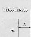
Table 1. Error Limits & Accuracy Clases
| Type |
± % Error for %In |
Phase difference ± for % In |
| Minutes |
Cent radian |
| 5 |
20 |
100 |
120 |
5 |
20 |
100 |
120 |
5 |
20 |
100 |
120 |
| 0.1 |
0.40 |
0.20 |
0.10 |
0.10 |
15 |
8 |
5 |
5 |
0.45 |
0.24 |
0.15 |
0.15 |
| 0.2 |
0.75 |
0.35 |
0.20 |
0.20 |
30 |
15 |
10 |
10 |
0.9 |
0.45 |
0.30 |
0.30 |
| 0.5 |
1.50 |
0.75 |
0.50 |
0.50 |
90 |
45 |
30 |
30 |
2.7 |
1.35 |
0.90 |
0.90 |
| 1.0 |
3.00 |
1.50 |
1.00 |
1.00 |
180 |
90 |
60 |
60 |
5.4 |
2.70 |
1.80 |
1.80 |
Table 2. Error Limits & Accuracy Clases
| Type |
± % Error for %In |
Phase difference ± for % In |
| Minutes |
Cent radian |
| 1 |
5 |
20 |
100 |
120 |
1 |
5 |
20 |
100 |
120 |
1 |
5 |
20 |
100 |
120 |
| 0.2S |
0.75 |
0.35 |
0.20 |
0.20 |
0.20 |
30 |
15 |
10 |
10 |
10 |
0.90 |
0.45 |
0.30 |
0.30 |
0.30 |
| 0.5S |
1.50 |
0.75 |
0.50 |
0.50 |
0.50 |
90 |
45 |
30 |
30 |
30 |
2.70 |
1.35 |
0.90 |
0.90 |
0.90 |
Table 3. Error Limits & Accuracy Clases
| Accuracy class |
± % Error for %In |
| % In |
50 |
120 |
| 3 |
3 |
3 |
| 5 |
5 |
5 |
For Protection Transformers
| Accuracy class |
± % Error for %In |
Phase difference ± for % In |
Composite error |
| Minutes |
Cent radian |
| 5P |
±1 |
±60 |
±1, 8 |
5 |
| 10P |
±3 |
-- |
-- |
10 |
Saturated Condition Of Current Transformer
The current transformer is saturated if the primary current, passing through the CT, is greater than the nominal rating of the CT.
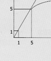
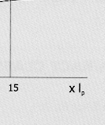
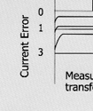
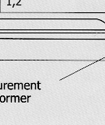
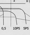
The linearity of current transformation, between the primary and secondary sides decreases, so error increases. The saturation of the transformer is inversely proportional to the load (Figure 1).
The difference between measuring and protection current transformers is their behavior when an overload occurs on the primary side. Measuring CT is saturated when there is a primary current overload. In order to protect the equipment, on the secondary side, protection CT will not saturate until there is a very high current on the primary side.
A Class 5P15 protection transformer indicates that it has an accuracy rating of +1% that it does not become saturated until the primary current reaches 15 times the nominal current rating of the CT.
In measuring transformers, the SAFETY FACTOR "Fs" parameter indicates the excessive amperage on the primary side current in relation to the current sent to the measuring device on the secondary side.
Figure 1
Application Note
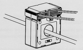
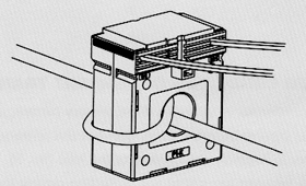
If the primary current is too small, to keep the same accuracy and output, we can add primary winding, but the rated turn’s ratio should be the same. For example, if the primary current is 50A, we can use 100/5A Current Transformer with the primary current be turned twice which help to keep the same rated turns ratio(l:50 = 2:100).
Important Note
- Improper selection, installation or operation can cause danger to personal security!
- Don't open the secondary circuit when the current is available in the primary circuit. Orit will cause high voltage which is dangerous to personal security

